With the continued growth and expansion of our towns and cities, the visual impacts of proposed developments are a fundamental consideration in planning decisions. Verified view montages (VVMs) are the key element in the assessment of visual impact and, therefore, are an integral part of any planning application. In fact, for large-scale residential schemes, verified view montages are considered a prerequisite and can be instrumental in helping to secure planning permission.
The support and confidence of planning authorities is critical in any planning application. To achieve this, it is crucial that verified view montages are created to a high level of verifiable accuracy. With this in mind, 3D Design Bureau work to a robust methodology in accordance with the latest industry standard guidelines. This ensures that verified view montages are produced to the highest level of quality and accuracy.
What are Verified View Montages?
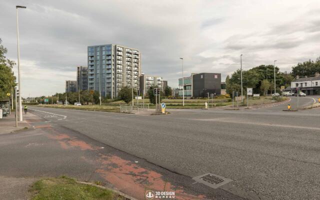
Verified view montages, also known as ‘Certified Views’ or ‘Accurate Visual Representations’, are technical photomontage images that accurately illustrate the visual impact that a proposed development may or may not have. They are produced to provide stakeholders, design teams and planning authorities with a technically accurate and photo-realistic view of a scheme in its intended location. Verified view montages generally range in distance from medium to long-range shots and can take in protected views.
Verified view montage accurately illustrating the visual impact that a proposed development may have.
Verified View Montages Methodology Overview
This summarised methodology has been prepared by 3D Design Bureau to explain the production of verified view montages (VVM). The preparation and presentation of reliable, verifiable visual information is a key component of the writing of Landscape Visual Impact Assessment reports.
It should be noted that VVMs are technical images and should be produced and used in a technically appropriate manner.
1. Project Planning
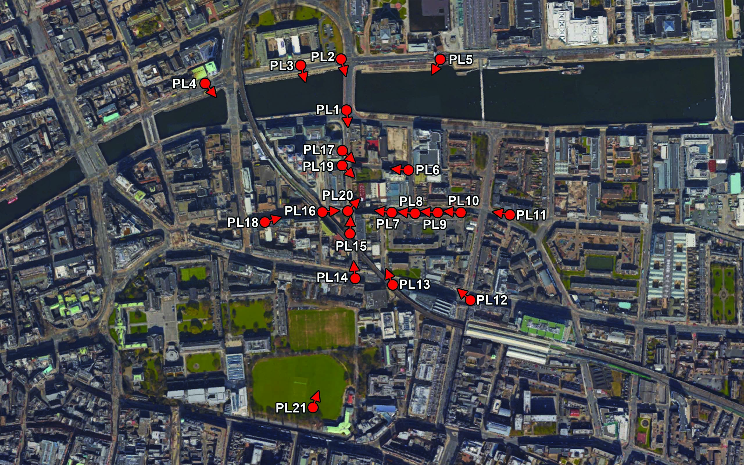
Following the appointment, a full list of suggested views is drawn up for review prior to visiting the site. This is carried out between 3D Design Bureau, the client, and the planning consultant.
Note: If an LVIA report is being written by a third-party planning consultant, the medium to long-range views will be guided by them. After obtaining a full list of viewpoint locations, it is reviewed, and a plan for the taking of baseline photographs is put in place.
Note: 3D modelling of the proposed scheme can, and usually is, commenced prior to the photographic site visit.
A full list of suggested views is drawn up for review prior to visiting the site.
2. High Resolution Baseline Photography
Every baseline photograph is captured in raw settings using a high-resolution digital SLR camera. This allows for the maximum possible information to be retained in the digital file. It also avoids the file being altered by any internal camera processing definitions, which retains the maximum control and fidelity on the end results.
The focal lengths used depend on the surrounding context and proximity to the desired area. 3D Design Bureau uses high-quality lenses with focal lengths that allow for capturing enough surrounding context without compromising quality and fidelity by avoiding excessive barrelling, distortion, or aberrations. All shots are taken horizontally with the use of a 50mm lens (where possible).
Note: Although the 50mm focal length represents the perceived scale of the human eye, it does not represent the human field of view and therefore should not necessarily be used to show the proposed development in its context.
On site and back in the studio, each photo location is correctly recorded and marked as follows
On-Site:
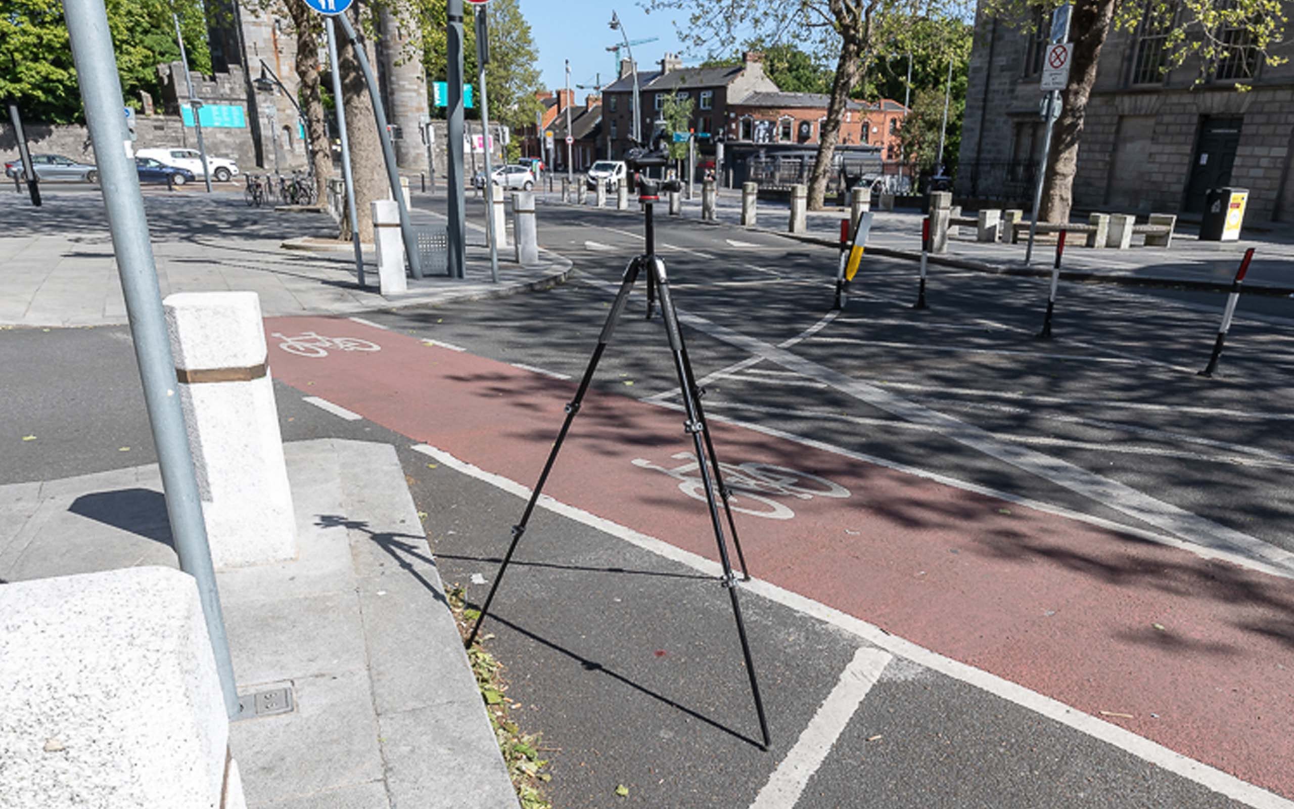
The tripod location on site is paint-marked and photographed in relation to existing elements. (pictured below)
The location of each photo is manually marked on a printed map while on site.
The camera height is recorded.
Upon completion of the baseline photo site visit, all photographs go through post-processing back in the studio. The full set of photos, along with a viewpoint location map, is issued to the client for review and to choose the best shots that will demonstrate the visual impact that the proposed scheme may/may not have.
The tripod location on site is paint-marked and photographed in relation to existing elements.
3. Baseline Photo Surveying
When all baseline photos are chosen for the VVMs, each one is marked up in the studio. Fixed reference points within each photo, such as parapet heights, kerbing, lamp posts, etc, are colour-coded on the baseline photos. All ‘marked up’ baseline photos are then issued to a qualified topographical surveyor for surveying purposes.
The survey team records the camera/tripod position using GPS and Total Station to an accuracy of +/-1cm Northing and Easting, and to an accuracy of +/- 2cm Elevation. The ‘marked up’ fixed reference points identified in each photo are then surveyed to establish the exact orientation of the view and to verify the photomontage process.
All ‘marked up’ baseline photos are then issued to a qualified topographical surveyor for surveying purposes.
4. 3D Modelling & Visualisation
3D Modelling
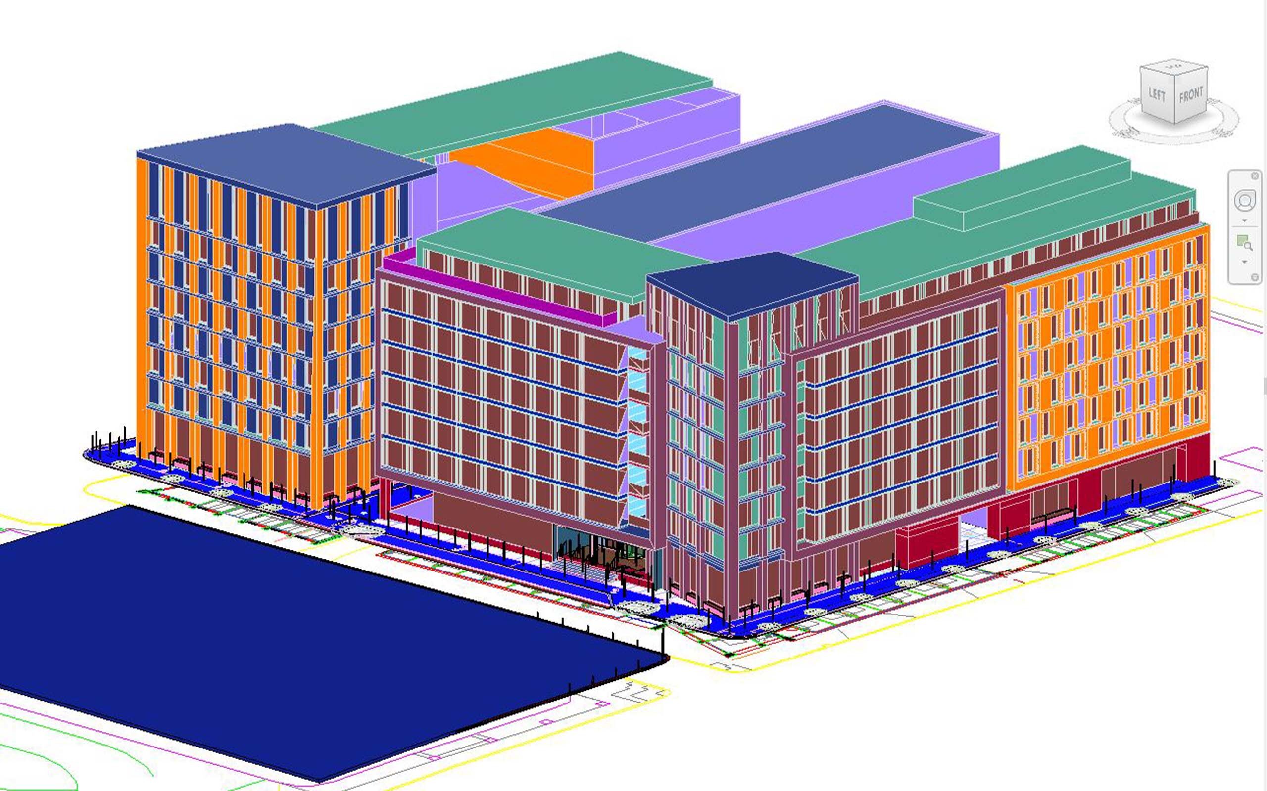
An accurate digital 3D model of the ‘proposed’ development is produced using the 3D software of choice. All of 3D Design Bureau’s 3D modelling is carried out within AutoDesk’s Revit. The digital 3D model is created from a combination of the third-party architectural, engineering and landscape drawings. All proposed model information is contained in one file, and it is always positioned relative to the existing site survey information.
The ‘marked up’ fixed reference points, which have been surveyed, are also modelled along with any other relevant survey information from the supplied top survey drawings. As stated above, the proposed 3D model and survey 3D model information are geospatially positioned relative to one another. This is imperative to ensure the accurate positioning and camera matching of the proposed digital 3D model within each chosen photo.
3D Visualisation
Once the digital 3D Revit model is complete, it is handed over to the 3D visualisation team for production. This production involves the matching of textures, lighting conditions and asset population for the proposed scheme. This ensures that the digital 3D model is visually represented as close as possible to the intended future ‘As Built’ development.
There are various 3D visualisation software that are widely used for this stage of the project. 3D Design Bureau uses 3D Studio Max for the visualisation process. This is accepted as the industry standard for architectural visualisation work and production of VVMs.
An accurate digital 3D model of the ‘proposed’ development is produced using the 3D software Revit.
5. Camera Matching, Rendering & Post Production
Following the completion of the 3D visualisation process (but in some instances prior to this), the following methodology is applied for views to be verifiable.
Camera Matching
All of the information recorded at the time of the baseline photographic site visit, that is, camera co-ordinates, angle of view, and direction of view, is programmed into the virtual camera within the 3D software package of choice – 3D Studio Max. Insertion of digital cameras within the software with matching attributes of the physical camera is carried out. This careful method ensures that the size, position, and height of the proposed development in each VVM is correct to an accuracy of 0.33% i.e. +/- 1mm on an A3 print.
Rendering
Following the camera matching and 3D visualisation process, the view is ‘rendered’ at high resolution and is placed onto its matching baseline photograph using Adobe Photoshop software. The mathematical accuracy is then double checked and verified by ensuring that existing ‘marked up’ fixed reference point features, which were also rendered, line up exactly in the photo.
Post Production
Next, the VVM specialist establishes which existing features, such as buildings, landscape and trees, are in the foreground of the proposed development and those that are in the background, i.e. which features will mask the development and which ones will appear behind the development. When it is found that the development is not visible due to foreground features, its extremities will be indicated with a red outline.
Verified view montage accurately illustrating the visual impact that a proposed development may have.
6. Results
The resulting VVM, having gone through this extensive procedure, is classed as an accurate and verifiable representation of the proposed development as viewed from the selected photo locations. This shows, as closely as possible, any future impact a proposed development may have on the surrounding environment and existing buildings, presenting a truly valuable tool for planning purposes.
High-quality, accurate verified view montages form the foundation of any LVIA or TVIA report, and can be instrumental in helping to secure planning permission.
Verified view montage accurately illustrating the visual impact that a proposed development may have.
LVIA and TVIA: their role in shaping planning decisions
Visual impact assessments can play an important role in the planning application process. Whether you have been instructed to provide an LVIA (Landscape Visual Impact Assessment) or TVIA (Townscape Visual Impact Assessment) by a planning consultant or a local council, submitting a complete and well-crafted report can have an impact on the outcome of your submission.
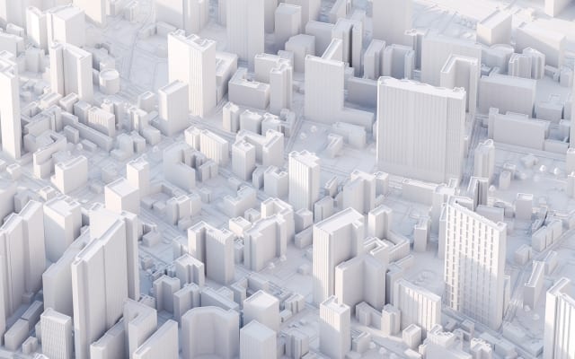
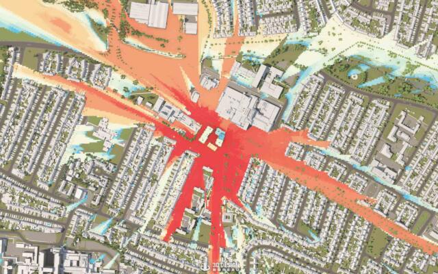
Zone of Theoretical Visibility: Reducing Risk and Cost in Property Development
Before a project even breaks ground, developers face a series of important steps that shape its viability. Beyond the challenges of the planning process, much of this work begins during the feasibility stage, where early decisions can save developers both time and money. One of the most effective tools at this stage is the Zone of Theoretical Visibility (ZTV).
We use cookies to ensure that we give you the best experience on our website. If you continue to use this site we will assume that you are happy with it.OkPrivacy policy